


Usually in the process of joystick use, there are two ways to achieve analog output signal: Hall sensor form and potentiometer type.
1, This article aims to clarify the basic implementation principle of Hall sensor, the differences, advantages and disadvantages between 2D Hall and 3D Hall.
Definition of Hall Effect:
Hall effect was discovered by physicist Hall in 1879. It defines the relationship between magnetic field and induced voltage. This effect is completely different from traditional electromagnetic induction.

——Image from the Internet
As shown above, when an electric current passes through a conductor located in a magnetic field (the shaded surface), the magnetic field exerts a force on the electrons in the conductor perpendicular to the direction of the electrons' motion, resulting in a potential difference in both directions perpendicular to the conductor and the magnetic inductance line.
When a magnetic field perpendicular to the current direction is applied to the semiconductor, electrons and holes in the semiconductor will be attracted by Lorentz force in different directions and aggregate in different directions. Electric field will be generated between the gathered electrons and holes. After the electric field force and Lorentz force are balanced, they will no longer aggregate. In this case, the electric field will make the subsequent electrons and holes subject to the electric field force and balance the Lorentz force generated by the magnetic field, so that the subsequent electrons and holes can pass through smoothly without deviation, which is the Hall effect. The voltage difference between the two sides is called Hall voltage.
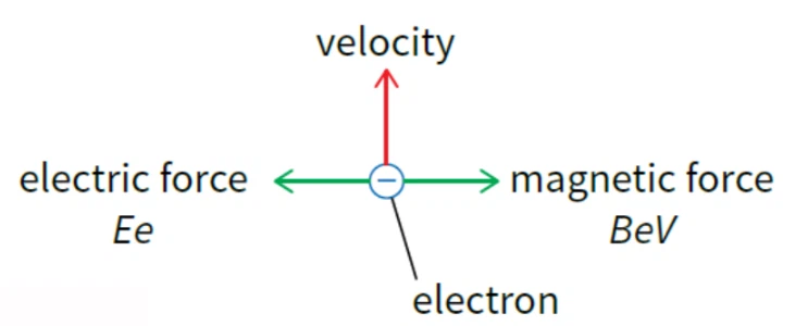
Schematic diagram
The electron creates a potential difference in the magnetic field resulting in a Lorentz force
Lorentz force F=qE+qvB/c
So the Hall field
UH=RH·I= -B·I /(q·n·c)
Application of Hall Effect:
Although Hall effect was discovered earlier, it was limited by the development of constant magnets and electronic components. Hall sensors first appeared around the 1970s.
The basic Hall sensor is designed as a highly reliable Hall chip integrated circuit by packaging the circuit chip of silicon single crystal material into an air-tight packaging structure.
However, due to circuit design problems, Hall chip used for the first time will produce large voltage changes due to temperature drift, which can not be applied in the actual industrial environment.
Later, until around the 1990s, some companies, such as MLX, used temperature compensation circuits to offset the influence of temperature related parameters in the magnetic field calculation formula, so that the magnetic field does not change with the temperature. Moreover, the Hall chip has realized programmable operation, which does not need to adapt the analog output set by the Hall chip to the usage requirements, and greatly broadens the usage scenario and scope of the Hall chip.
Hall chip began to be widely used in industrial and vehicle environment, used to judge the parameters of displacement and rotation Angle, and convert them into analog output.
Following MLX Company, many IC manufacturers at home and abroad joined in the development of Hall chip. The conventional Hall chip used now is usually made of multiple Hall chips superimposed for redundancy judgment, which greatly improves the resolution and accuracy of analog output.
Use of Hall in the handle:
Early industrial handles achieved analog output through the rotating structure of the handle, which pushed the bullet to drive the hydraulic valve. There will be deficiencies in intelligent control and logic design, and the hydraulic device will inevitably have oil leakage phenomenon, which cannot be used in the scene with high pollution level requirements or in the scene requiring a clean environment.

Hydraulic use of the bullet form
——Image from the Internet
Hall was first used in joysticks by Danfoss, a German manufacturer. Its main products are JS1, JS1000 and so on.
Hall chip manufacturers are commonly used in the handle, including MLX, TI, McGahn and so on.
There are differences between 2D plane hall and 3D hall according to different use methods.
Difference between 2D Hall and 3D Hall:
Normally, the use of Hall in the handle is divided into rotary and displacement and swing. The rotary type is 2D Hall, and the displacement and swing type is 3D Hall.
* Note the use of magnetic steel:
Regardless of the Hall form, there are two critical control requirements to achieve the stability of the Hall's work.
The first one is the distance between the magnetic steel and the Hall center, which varies according to different Hall chip models. It is generally about 1~5mm.
The second is the magnetization size of magnetic steel, according to the Hall chip model is different, generally in dozens of mT to hundreds of mT.
If either of the two parameters is out of range or the deviation is large, it will cause the instability of Hall chip, resulting in output mutation or output deviation.
In addition, in general, magnetic steel will not cause output deviation due to demagnetization during its long-term use, and its key parameter is the coercivity of magnetic steel. Coercivity refers to the magnetic induction intensity B does not return to zero when the external magnetic field returns to zero after saturation magnetization of magnetic materials. Only by adding a magnetic field of a certain size in the opposite direction of the original magnetization field can the magnetic induction intensity return to zero, which is called coercive magnetic field or coercive force.
In general, the coercivity of magnetic steel requires Hcb≥850KA/m; Intrinsic coercivity Hcj≥955KA/m. The main influencing factor is the material of magnetic steel. Generally, the coercivity of ferrite material is small, which will lead to demagnetization of magnetic steel for a long time. And the coercivity of NdFeb material is larger, usually non-long-term high temperature (above 60~80℃) under the conditions of use, the use of about five to ten years is more than enough.
The magnetic steel used for the handle is usually N35 Ndfeb magnetic steel.
Other controlled elements of magnetic steel are remanence Br and maximum magnetic energy product BH(max).
1. Rotary type:
Rotary Hall is usually set in the center of the axis of rotation, and the direction of magnetization is radial. When the handle shaft is turned, the Hall voltage is generated due to the change in magnetic flux through the Hall sensor.
The advantages of this method of use are:
1. Good voltage symmetry;
2. Low realization difficulty;
3. In the case of dual shaft handle, XY axis interference is small;
4. The single-axis handle takes up less space.
5. Low magnetization difficulty.
6. Rotation Angle can be large (less than 360°)
The disadvantages are:
1. When the dual-axis handle is realized, it needs to occupy relatively large space;
2. Must be used in the center of rotation.

Type of rotation
1. Displacement formula:
Usually, the use of displacement is also the use of 3D Hall, such as the first flag MT1531 chip. Usually the direction of magnetization is radial. In this way, the magnetic field steel should have a magnetic flux of 0mT at the midpoint, which is maximum on both sides. When magnetic steel is magnetized in this way, it is necessary to have requirements on the magnetization uniformity on both sides of strip magnetic steel or curved magnetic steel. If the magnetic size is different, the magnetic flux distribution will be uneven, resulting in the linear deviation of output on both sides when the handle is shaken.
Advantages:
1. The structure is simple and the displacement hall price is low;
2. The structural phase of the magnetic steel that is difficult to place in the center of rotation is better;
3. Flexible structure, can do more varieties of structure.
Disadvantages:
1. Magnetic steel needs magnetizing symmetry;
2. In general, it is very difficult to realize linear symmetry of displacement formula;
3. The rotation Angle should not be too large; (usually not exceeding 40°)

——Image from MLX90333 specification
1. Swing type:
Oscillating Hall is a common realization of biaxial hall. It realizes dual-axis or even multi-axis output of one chip by superimposing multiple Hall chips on a Hall sensor.
Usually, the direction of magnetic steel magnetization is axial magnetization, and the axial magnetization of circular magnetic steel will greatly reduce the difficulty of magnetization.

——Image from MLX90333 specification
For Hall sensors, although a single 3D chip is more expensive than a 2D chip, the cost of implementing a biaxial output is relatively lower than using two 2D chips.
Advantages:
1. Magnetic steel has low magnetization difficulty. Low assembly difficulty;
2. Biaxial realization cost is low;
3. The horizontal space of the handle is less occupied;
Disadvantages:
1. The offset requirement of Hall patch is relatively high, and the offset requirement of SMT is generally not more than 1/2 of the welding foot; Otherwise, there will be a large biaxial interference (that is, when pushing one axis, the other axis has output fluctuations, 3D Hall cannot avoid biaxial interference, but generally within the output deviation range is considered qualified)
2. The cost of achieving uniaxial output will be higher;
3. The rotation Angle is smaller than the displacement type (generally not more than 30°);
The HJ8 handle of Shanghai Chen Gong Electric Control uses the 3D Hall of MLX90333.
Ii. Factors affecting Hall output deviation:
Generally speaking, the factors that affect Hall output voltage are mainly the following reasons. Generally speaking, since the chip rarely goes bad, the causes of output voltage deviation are mainly analyzed from the magnetic flux changes:
1. Changes in magnetic flux caused by magnetic steel:
Magnetic steel will change the magnetic flux and thus the output voltage due to various reasons, such as:
A. Poor protection leads to the adsorption of iron powder on the magnetic steel, resulting in the change of magnetic flux.
B. Improper fixing of magnetic steel leads to the loosening of magnetic steel;
C. Hidden cracks exist when magnetic steel is riveted or fixed, which can lead to cracks and magnetic flux changes after high and low temperature.
Ways to avoid:
These factors need to be analyzed and improvement measures followed up in the FEMA of the design and process.
2. Magnetic flux changes caused by external causes:
Generally, the magnetic flux through Hall chip changes due to circuit fluctuations caused by external magnetic field or voltage impact, thus affecting the output.
Ways to avoid:
EMC test was carried out, and shield shield was used to increase the shielding of Hall chip.
3. Output deviation caused by mechanical structure:
After long-term use, the increase of mechanical clearance leads to the increase of output deviation.
Ways to avoid:
Optimize the structural design.
4. External input voltage non-regulated power supply:
Generally speaking, the nominal Hall input voltage of the Hall handle manufacturer is 5.0Vdc±0.5V, but in practice, this voltage refers to the voltage that drives the Hall sensor. If the calibration output voltage value is 0.5~2.5V~4.5V output, input 5.5V voltage, then the median output voltage will be 2.75V, beyond the range of the median requirements. Therefore, customers are generally told to use a regulated power supply. The power supply deviation is generally ±0.2V with conditions in the best range of ±0.1V.


