Latest Products


Contact Us
- 2F Building E, 1355 ChengBei Road, Jiading, Shanghai, China 201807
- wangyi@halljoystick.com
- +8618917316571
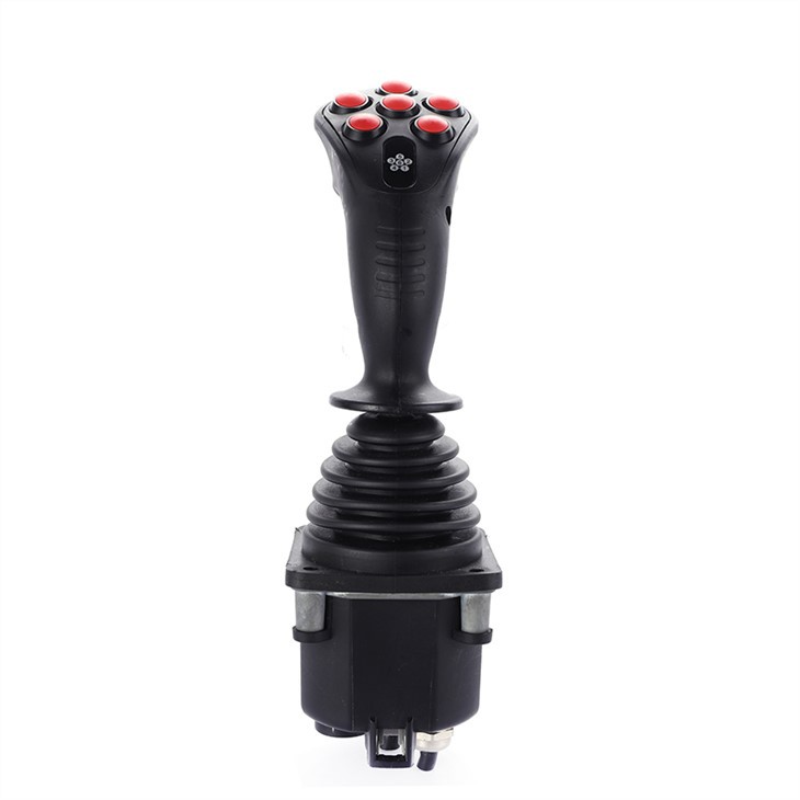


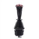
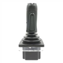
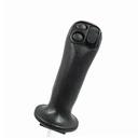
Hand Grip Hall Effect Joystick with Buttons
Using ergonomic principles,specially designed for the construction machinery industry.
Two angular displacement detection methods of non-contact Hall sensor and long-life potentiometer.
Description
HJ60 series Multi-functional Cobra Joystick
Multi-operational Cobra Control joystick can be used to operate complex functions with incorporated push button switches,thumb wheel and seesaw motion potentiometer.
Product Features
Using ergonomic principles, specially designed for the construction machinery industry.
Two angular displacement detection methods of non-contact Hall sensor and long-life potentiometer.
A variety of different types of handles are available for selection.
The number and position of buttons can be customized.
Optional CAN bus output.
Application range
This series of products are mainly used in cranes, loaders, forklifts, excavators, tractors, harvesters, Garbage truck etc.


Technical Information
Electrical parameters
Potentiometer type
Power supply voltage | <36Vdc |
Total resistance value | 2KΩ, 4KΩ, 5KΩ, 10KΩ |
Electrical angle | ± 18 ° |
Median voltage | 48% ~ 52% (relative power supply voltage) |
Median dead zone angle | ± 2.5 ° |
Potentiometer maximum voltage | 32Vdc |
Potentiometer allows maximum power consumption | 0.25W |
Hall type
Power supply voltage | 5.0 ± 0.5Vdc |
Power supply current | <11mA (each Hall sensor) |
Limit allowable overvoltage | 20Vdc |
Reverse limit allowable voltage | -10Vdc |
Linear error of output voltage | <± 0.2V |
Direction switch
Load capacity | 2mA @ 30Vdc (resistive load) |
Starting angle | ± 5 ° |
Contact resistance | <200Ω |
With conversion circuit
Power supply voltage range | 18 ~ 36Vdc (U 21 ~ U 24) |
9 ~ 36Vdc (current output) | |
Power consumption current | <20mA |
Maximum output current | 10mA (at standard voltage output) |
CAN bus type
Power supply voltage | 9 ~ 36Vdc |
CAN version CAN | 2.0B |
Protocol | J1939 |
connector | 6-pin socket (Deutsch) |
Micro Switch
Load capacity | 4A @ 30Vdc (resistive load) |
Service life | more than 30 million times (mechanical) |
200,000 times or more (electrical) | |
Insulation resistance | > 100MΩ (500Vdc insulation resistance meter) |
Starting angle | ± 3 ° ~ ± 5 ° |
Mechanical parameters
Rocking angle | ± 20 ° |
Mode of operation Automatic | spring return |
Starting force | 5N |
Maximum operating force | 11N |
Limiting force | > 300N |
Service life | > 2 million times (potentiometer type) |
> 5 million times (Hall type) | |
Weight | 475g (no upper end) |
Environmental parameters
Working temperature -30 ℃ ~ + 70 ℃ |
Storage temperature -40 ℃ ~ + 85 ℃ |
Protection grade IP65 (above the installation panel) |
Product selection
HJ60series


Operation method
1A | single axis front-back direction |
2AP | 2-axis operate in cross direction |
2AC | 2-axis operate in round direction |
Spring selection
L | starting force 4.5N |
M | Starting force 5N (default) |
H | starting force 9N |
Output signal
Potentiometer type (power supply voltage is less than 36Vdc)
P051 | 5KΩ potentiometer 0% ~ 100% Vdc voltage output | |
P052 | 5KΩ potentiometer 10% ~ 90% Vdc voltage output | |
P053 | 5KΩ potentiometer 25% ~ 75% Vdc voltage output | |
| P101 | 10KΩ potentiometer 0% ~ 100% Vdc voltage output |
Ordinary Hall type (supply voltage 5Vdc)
H51 | Single Hall per axis 0.5 ~ 2.5 ~ 4.5Vdc voltage output |
H52 | single Hall per axis 0 ~ 2.5 ~ 5Vdc voltage output |
H53 | Single Hall per axis 1.25 ~ 2.5 ~ 3.75Vdc voltage output |
H54 | Single Hall per axis 1.0 ~ 2.5 ~ 4.0Vdc voltage output |
H55 | Single Hall per axis 1.15 ~ 2.5 ~ 3.85Vdc voltage output |
2H51 | Double Hall for each axis 0.5 ~ 2.5 ~ 4.5Vdc voltage output |
2H52 | Double Hall for each axis 0 ~ 2.5 ~ 5Vdc voltage output |
2H53 | Double Hall for each axis 1.25 ~ 2.5 ~ 3.75Vdc voltage output |
2H54 | Double Hall for each axis 1.0 ~ 2.5 ~ 4.0Vdc voltage output |
2H55 | Double Hall for each axis 1.15 ~ 2.5 ~ 3.85Vdc voltage output |
Remarks: The Hall type can also be used with a wide voltage of 9 ~ 36V, the voltage output is the same as above; the selection is preceded by an ordinary Hall type with "W", such as W2H51, representing a wide voltage, redundant Hall for each axis, 0.5 ~ 2.5 ~ 4.5 Vdc voltage output.
With conversion circuit
U21 | power supply voltage 18 ~ 36Vdc, -10V ~ 0V ~ + 10V voltage output |
U22 | power supply voltage 18 ~ 36Vdc,+ 10V ~ 0V ~ + 10V voltage output |
U23 | power supply voltage 18 ~ 36Vdc, -5V ~ 0V ~ + 5V voltage output |
U24 | power supply voltage 18 ~ 36Vdc,+ 5V ~ 0V ~ + 5V voltage output |
I21 | power supply voltage 9 ~ 36Vdc, two-wire system 4mA ~ 12mA ~ 20mA current output |
I22 | power supply voltage 9 ~ 36Vdc,two-wire system 20mA ~ 4mA ~ 20mA current output |
CAN bus type (power supply voltage 9 ~ 36Vdc)
J33 | CAN 2.0B bus output,source address is 33 |
J34 | CAN 2.0B bus output,source address is 34 |
J35 | CAN 2.0B bus output,source address is 35 |
J36 | CAN 2.0B bus output, source address is 36 |
Attention please:If you want to choose 2 can bus joystick used on a same equipment,please choose 2 different source address.
Other
NA (no analog signal output)
Micro switch (not available when CAN bus is output)
MS00 | without micro switch |
MS12 | with 4A front and back position micro switch not available for dual-axis cross direction operation |
Upper end of handle
HA | HA handle no button on top |
HAS | HAS handle with button on top |
HD | HD handle no button on top |
HDS | HDS handle with button on top |
HDR | HDR handle with rocker on top |
KGDN | KG handle with deadman switch, no rocker |
KGDR | KG handle with deadman switch and seesaw |
SS | For details please refer to the description of the grip of the SS/SA/SP handle |
Outgoing way
D | Dechi connector (only CAN bus output) |
A | AMP connector |
Dimensions

Product Installation


Electrical Installations
Deutsch (Deutsch) socket
Pin number CAN output color
1 Ground (GND) black |
2 Power supply (VCC) red |
3 CAN high yellow |
4 CAN low green |
5 CAN shield N / A |
6 Empty (N / A) N / A |
AMP connector
16 core interface
Pin No. P Potentiometer Series H Hall Series U Conversion Circuit Voltage Conversion Circuit Voltage
1 Y-axis front direction switch Button switch 4 Button switch common terminal Button switch common terminal |
2 Empty (N / A) button switch 3 Button switch 1 Button switch 1 |
3 X axis potentiometer left end button switch 2 button switch 2 button switch 2 |
4 Slide end of X-axis potentiometer Button switch 1 Button switch 3 Button switch 3 |
5 Right end of X-axis potentiometer Top button Push button switch 3 Push button switch 3 |
6 X axis potentiometer center end button switch 5 button switch 5 button switch 5 |
7 X axis switch common end button switch 6 button switch 6 button switch 6 |
8 X-axis left direction switch Safety switch Top button Top button |
9 Y-axis potentiometer rear button switch 9 safety switch safety switch |
10 Y-axis potentiometer sliding end button switch 10 safety switch safety switch |
11 Front end of Y-axis potentiometer Button switch common terminal X-axis left direction switch X-axis left direction switch |
12 Y-axis potentiometer center end safety switch X-axis right direction switch X-axis right direction switch |
13 Y axis switch common end empty Y axis back direction switch X axis switch common end |
14 Y-axis rear direction switch empty Y-axis front direction switch Y-axis rear direction switch |
15 X axis right direction switch empty switch common Y axis front direction switch |
16 empty (N / A) Y-axis switch common |
12 core interface
Foot number P potentiometer series H Hall series (5V)
1 Button switch 4 + 5V power supply (redundant) |
2 Button switch 3 0V power supply (redundant) |
3 Button switch 2 + 5V power supply |
4 Button switch 0V power supply |
5 Top button Y axis output (redundant) |
6 Button switch 5 X axis output |
7 Button switch 6 X-axis output (redundant) |
8 Safety switch Y axis output |
9 Button switch 9 Z1 axis output |
10 Button switch 10 Z2 axis output |
11 Button switch common Z1 axis output (redundant) |
12 Safety switch Z2 axis output (redundant) |
※ Standard Hall output, use 3/4/6/8 pin outlet
8-core interface
Footnote H Hall Series Conversion Circuit
1 Front direction micro switch common terminal VCC |
2 Front direction micro switch output GND |
3 Output terminal of micro switch in the rear direction X-axis output |
4 Y axis output of the common terminal of the back direction micro switch |
5 Left side micro switch public end Out com |
6 Output terminal of micro switch in the left direction NA |
7 Micro switch output terminal in the right direction NA |
8 Common terminal of the micro switch in the right direction NA |


Hot Tags: hand grip hall effect joystick with buttons, China, suppliers, manufacturers, factory, customized, bulk, low price
You Might Also Like


